How do I replace my defective gear?
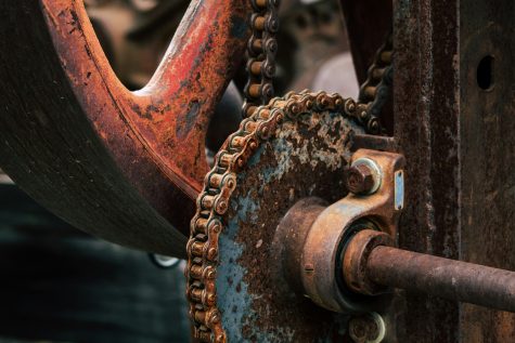
When a gear tooth breaks, it can stop your machine. If the manual is lost and the manufacturer can’t supply parts, you need a replacement. Even if you know the gear’s parameters, finding the right one can be tricky.
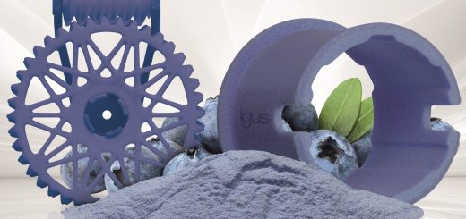
A simple solution is using a 3D printing service to create custom gears from wear-resistant materials quickly and cost-effectively and our online configurator lets you design gears without needing a CAD system.
Intensive testing shows that 3D printed gears using laser sintering powder can be more durable than milled or injection-moulded gears. We can predict their life cycle and compare them to other manufacturing options.
Configuring a Gear
The igus gear configurator allows you to create a gear model with accurate involute geometry and rounded tooth roots. Many CAD programs oversimplify this, leading to rough running and early wear.
The configurator offers options for various shaft shapes and single or double gears. You need to determine key parameters and measure other dimensions with a sliding calliper gauge.
For example, the igus 3D printing service works with a precision of ± 0.1mm. For a drill hole with a nominal diameter of 10mm, it could be 10.1mm or 9.9mm. To ensure proper engagement, you might specify the hole as 10.05 or 10.1mm. Alternatively, igus can perform rework and hole reaming.
Determining Gear Parameters
The key figure for spur gears is the gear module (m), is millimetres. The module describes the gear pitch adjusted by π. Gears with the same module can mesh together. The outside pitch circle diameter (d) is calculated from the module (m) and tooth number (n): d = m*n.
Measuring the Outside Pitch Circle Diameter
This diameter can be approximated by inserting two dowel pins into the gear teeth and measuring the distance between them with a sliding calliper gauge. Subtract one pin diameter from this value. This method works best with even numbers of teeth.
Standardised Modules
The module in preferred rows is standardised (DIN 780). Machine-manufactured gears usually follow these values. If your measured value matches the table, it’s a good sign.
Specifying the Gear Module Based on Tip Diameter
Measuring the tip diameter (the gear’s outer diameter) is easier. The configurator uses the tooth number and tip diameter to calculate the gear module. If the calculated module isn’t standard, check for measurement errors. For example, if m = 1.96, the gear likely has a module of 2mm.
Profile Shift
In some cases, a profile shift can affect tooth geometry. The configurator doesn’t account for this, which can cause slight deviations in module calculation.
Once configured, you can download the 3D model for free in STEP format for further use or component orders from the igus 3D printing service. You can also download a model in STL format for printing on your own 3D printer.
Selecting a Material and Ordering the Gear
The iglidur i3 sintering material is ideal for spur gears, lasting longer than milled or injection-moulded gears made of POM. This material contains solid lubricants, increasing wear-resistance and resilience, reducing friction and tooth wear. For worm gears, the iglidur I6 laser sintering material is better.
Upload the STEP model to our 3D printing service, select the right material, and get an immediate price and delivery time. You can order directly or send a query. In two to three business days, you’ll receive your ready-to-install gear and can resume work.
Discover more on 3D Printing.